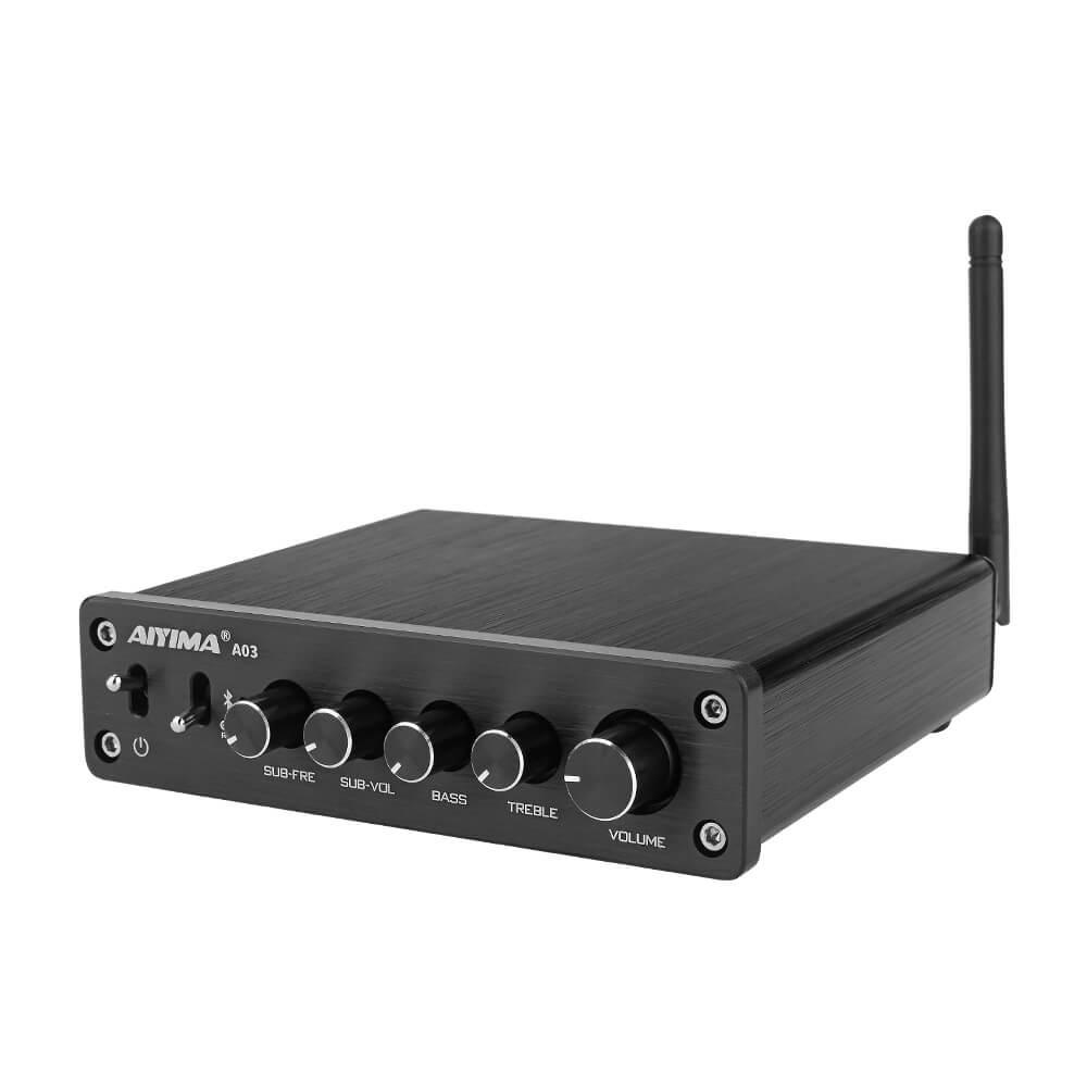
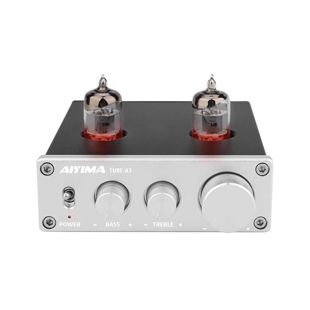
First you need understand what is a power amplifier?
Explain that the power is amplified, not the current or the voltage, right?
How it works: The power of the power supply is converted into a current that changes according to the input signal through the current control of the transistor, and the current of the collector is always the amplification of the base current, so the amplified current can be obtained , And then after continuous current and voltage amplification, power amplification is completed.
Capable of converting stagnant input power into AC output power.
The transistor operates under large signal operating conditions, and the operating point will swing up and down significantly. Once the operating point is outside the input or output linear region, non-linear distortion occurs.
The voltage amplification circuit is to load to obtain an undistorted voltage signal. The main indicators of Tyren are voltage gain, input and output impedance, etc., but the output power is not necessarily large. Amplifiers are different. Amplifiers require a certain amount of undistorted output power. They usually work in a large signal state, so they must have high output power, high efficiency, and low nonlinear distortion. Another serious issue is heat dissipation.
A power amplifier is an amplifier that can produce a maximum power output to drive a certain load under a given distortion rate.
Power amplifier classification
- Class A
- B
- AB
- D category
- T type
Class A amplifier
- The operating point is set near the midpoint of the load line, and the current drawn from the power supply is constant.
- The actual efficiency is only 25% at the maximum, which can be operated by single tube or push-pull.
- The circuit is simple and easy to debug, but the efficiency is low and the transistor is effective.
- Within the linear range of the amplifier's operating characteristic curve, transient distortion and alternating distortion are small.
Class B amplifier
- When there is no output signal input, the output end consumes almost no power.
- High efficiency, the amplifier has a section that works in the non-linear region, and the "crossover distortion" is large.
- When the signal is between -0.6V ~ 0.6V, Q1 and Q2 cannot be turned on.
Class AB amplifier
- High output power and medium power consumption.
- Transistor on-time is longer than half cycle, and two tubes must be used for push-pull.
- Alternating distortion is large, which can offset harmonic distortion.
Class D amplifier
- Has a very high efficiency, which can usually reach more than 85%.
- Small size, which can save a lot of space than the analog amplifier circuit.
- No crack noise is switched on.
- Low distortion, good frequency response curve, few peripheral components, easy to design and debug.
Class T amplifier
- The power output circuit is the same as the pulse width modulation class D power amplifier.
- The switching frequency of the power transistor is not fixed.
- Wider dynamic range and flat frequency response.
How a classic Class D power amplifier works
As shown in the figure below, the classic power amplifier is mainly composed of three parts: pulse width modulator, switching amplifier, and low-pass filter. The middle figure is a schematic diagram of the class D power amplifier. The triangle wave oscillator, a comparator composed of an operational amplifier, and an input audio signal constitute a pulse width controller; two output MOSPET tubes constitute a switching amplifier; Lf and Cf constitute a low-pass filter for recovering the audio signal. The driver stage is used to drive the switching amplifier. Under the action of the driver stage, the output of the amplifier stage is switched between Vdd or -Vdd, so the final output of the Class D amplifier is a high-frequency square wave. The switching frequency (Fsw) of most Class D amplifiers is 250kHz to 1.5MHz. The audio input signal performs pulse width modulation on the output square wave, that is, the audio input signal is compared with the triangular wave (or sawtooth wave) generated by the internal oscillator to obtain a PWM signal. This modulation method is usually called "natural sampling", and the triangle wave oscillator is the sampling clock. The duty cycle of the output square wave is proportional to the input signal level. The following figure shows the relationship between the input audio signal and the output signal of the switching amplifier.

Bridge output
Many Class D amplifiers use a bridge output stage. -A bridge output uses two switching amplifiers as shown in Figure 2 as the output stage and drives the load differentially. This type of load connection is often referred to as bridge-to-load (BTL). As shown in the figure below, the bridge structure works by converting the load's conduction path, so its load current can flow in both directions without the need for a negative power supply or a DC blocking capacitor. When the pulse value is positive, the field effect transistors T1, T4 are turned on, T2, T3 are turned off; when the pulse is negative, T2, T3 are turned on, and T1, T4 are turned off.
The output of the bridge output requires an external LC filter to extract low frequency audio signals and prevent high frequency energy from being dissipated on the load.

No output filter
The need for an external LC filter not only increases the total cost and board space, but also introduces additional distortion due to the non-linearity of the filter components, thus becoming one of the main disadvantages of traditional Class D power amplifiers. At present, many Class D amplifiers use advanced "filter-free" modulation schemes, thereby eliminating or minimizing the need for external filters.
Focus on Audio


Leave a comment
This site is protected by hCaptcha and the hCaptcha Privacy Policy and Terms of Service apply.