How Class D Amplifiers Work
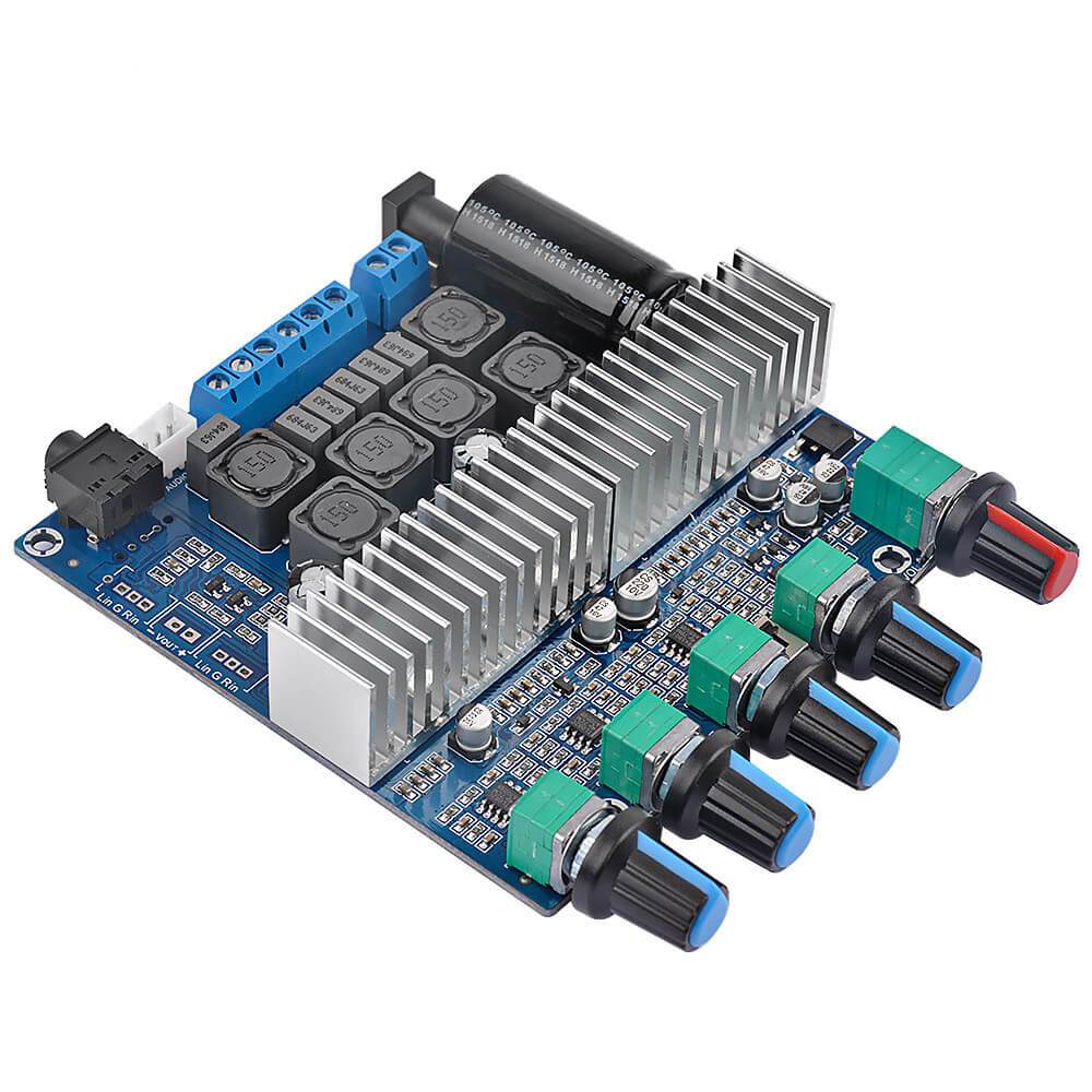
Class D amplifiers refer to Class D audio power amplifiers (sometimes called digital amplifiers). By controlling the ON / OFF of the switch unit, the amplifier driving the speaker is called a Class D amplifier. Class D amplifiers were first proposed in 1958, and have become increasingly popular in recent years. It has been available for many years. Compared with the general linear AB power amplifier circuit, the D power amplifier has the characteristics of high efficiency and small size.

The design considerations of Class D amplifiers are completely different from those of AB amplifiers. At this time, the linearity of the power amplifier tube is no longer significant, the more important switching response and saturation voltage drop. Because the pulse frequency processed by the power amplifier tube is dozens of times of the audio signal, and it is required to maintain good pulse front and back edges, the switching response of the tube is better. In addition, the efficiency of the whole machine lies in the pipe consumption caused by the saturation pressure drop of the pipe. Therefore, not only the saturation tube pressure drop is high, the heat dissipation structure of the power amplifier tube can also be simplified. A few years ago, the high-frequency and high-power tube was expensive, which limited the development of Class D amplifiers to a certain extent. Now MOSFETs with low current control and high current have been widely used in the industrial field, especially UHC MOSFETs have been applied to Hi-Fi power amplifiers in recent years, and the obstacles of the device have been eliminated.
Modulation circuit is also a special link of class D power amplifier. To modulate audio below 20KHz into a PWM signal, the frequency of the triangle wave must reach at least 200KHz. If the frequency is too low to meet the same THD standard, the requirements for the components of the passive LC low-pass filter are high and the structure is complicated. The frequency is high, the jaggedness of the output waveform is small, it is closer to the original waveform, and the THD is small. In addition, the filter can be made of inductors and capacitors with low values, small size, and relatively poor accuracy requirements, and the cost is reduced accordingly. However, at this time, the switching loss of the transistor will increase as the frequency rises. The high-frequency loss in the passive device and the skin effect of the radio frequency will reduce the overall efficiency. Higher modulation frequencies will also cause radio frequency interference, so the modulation frequency cannot be higher than 1MHz.
At the same time, the shape of the triangular waveform, the accuracy of the frequency, and the jitter of the clock signal will affect the distortion of the recovered signal that is different from the original signal. So to achieve high fidelity, many of the same considerations as digital audio fidelity have arisen.
Another factor that has a lot to do with sound quality is the passive filter located between the drive output and the load. The low-pass filter works under high current, and the load is the speaker. Strictly speaking, the impedance change of the speaker should be taken into consideration when designing, but it is not feasible to specify the speaker as an amplifier product, so the combination of Class D amplifier and speaker is more enthusiastic. It is actually proved that when the distortion requirement is below 0.5%, the second-order Butterworth flattened response low-pass filter can meet the requirements. If higher requirements are required, a fourth-order filter is required. At this time, issues such as cost and matching must be considered.
In recent years, general-purpose Class D power amplifiers already have integrated circuit chips, and users only need to design low-pass filters as required.
AIYIMAFocus on Audio


Leave a comment
This site is protected by hCaptcha and the hCaptcha Privacy Policy and Terms of Service apply.