To make a power amplifier is not a simple matter. First, we must understand some basic requirements, then the manufacturing process, and finally the circuit design.
Three basic requirements for making power amplifiers
Have enough output power
- The 3dB pass band is 300 ~ 3400Hz, the output sine signal has no obvious distortion
- Maximum undistorted output power ≥1W
- Input impedance> 10kΩ, voltage magnification is 1 ~ 20 continuously adjustable
- Low frequency noise voltage (below 20kHz) ≤ measured when the voltage amplification factor is 10 and the input terminal is short-circuited to ground
- When the output power is 500mW, the measured power amplifier efficiency (total power consumption of the output power amplifier) ≥50%

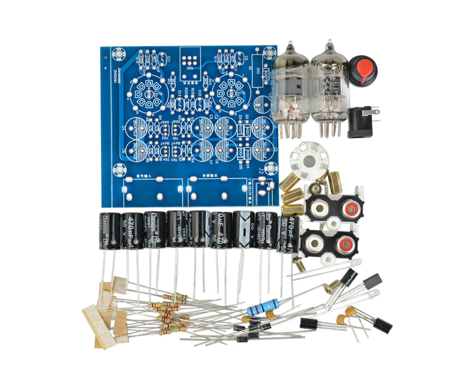
DIY Amplfier
High efficiency:
Design and produce a signal conversion circuit with an amplification factor of 1, which converts the signal output from the two ends of the power amplifier to a single-ended output, and is used for external test instruments after RC filtering.
Low nonlinear distortion:
Design and manufacture a device for measuring the output power of the amplifier, which requires a 3-digit display with accuracy better than 5%. The maximum undistorted output power is ≥1W.
Six considerations for the production process
Making a power amplifier requires not only a reasonable circuit, but also craftsmanship. Otherwise, loudspeaker noises or howling caused by self-excited oscillation may appear in the speaker. When instructing friends to make discrete components and integrated power amplifiers with higher power, they analyzed and summarized the above two problems, and started to improve from the circuit structure and layout, and achieved good results. In general, the following aspects should be noted when making a power amplifier:
- Choose a stable and solid chassis, preferably a metal structure, to avoid the internal circuit short circuit or external interference noise caused by the deformation of the chassis.
- Reasonably arrange the position of each unit in the chassis and pay attention to the center of gravity of the whole machine. The power supply part should be far away from the small-signal amplifier circuit. It is better to isolate the power supply part from the amplifier circuit. The method is to put the power supply part in a separate chamber made of metal to reduce the influence of the power supply on the amplifier circuit.
- Before the components are put on the board, use a tool to scrape off the oxide layer on the lead, and use a digital meter to measure whether the actual value is consistent with the nominal value and whether the error is within the allowable range. After the component is put on the board, it should be carefully checked for any wrong soldering or missing soldering, and if there is, it should be discharged in time.
- When soldering, you should select an electric soldering iron with appropriate power according to the size of the components and use high-quality solder and low corrosive flux to ensure that the solder joints are of suitable size, smooth and bright, and there is no false soldering or virtual soldering.
- Each section in the machine (including signal input and output sockets) can not be grounded separately, but the whole machine should be grounded one point, that is, after finding the ground point on the chassis, use thick black wires from each board The ground line leads out and gathers at this point. When the secondary ground point is separated from the chassis, use a multimeter to measure any point on the circuit board and the visible resistance value should be infinite.
- After the units are fixed in the chassis, use nylon buckles to fasten the connection harnesses and fix them accordingly.
After the machine is completed, use a multimeter to measure the resistance between each key point and the ground. The resistance between the corresponding point of each channel and the ground should be the same or very close. If an abnormality is found, there is generally a wrong solder in the circuit. , Due to missing soldering or incorrect values of the components used, it is generally not difficult to find the problem after careful inspection or measurement. If no problems are found in the above inspection, power on the whole machine (no audio can be connected at this time) and observe whether there are abnormalities (such as overheating of components, smoke, and whether the protection relay can be properly attracted, etc.).

DIY Amplifier Part
Principles of circuit design
When designing the power amplifier circuit, the circuit should be designed to be simple. If you want to pursue the original taste of music, try to reduce the link between the weapon signal input circuit and the power amplifier circuit, such as tone, balance or other functional circuits. If you like to modify the music, in addition to adding the above circuits, you can also add circuits such as BBE, 3D and SRS that can greatly modify the music signal. In arranging the location and wiring of components on the circuit board, please follow the following principles:
- According to the signal transmission path, arrange the positions of the components on the circuit board in order from small to large, and try to shorten the distance between the components (the jumper can be used when the distance is too large or encounters obstacles), To reduce the introduction of external interference.
- In the power supply line, it is not allowed to cross-arrange the large-current printed circuits or wires in the middle or near the small current path, so as not to cause interference to the small current line.
- The path (printed lines or wires) through which large current flows on the circuit board should be designed to be wider so that the current can flow smoothly.

TPA3116D2 Circuit Diagram
Focus on Audio

Leave a comment
This site is protected by hCaptcha and the hCaptcha Privacy Policy and Terms of Service apply.